

- 2021-11-10
- Posted by: manager
- Category: BLOG
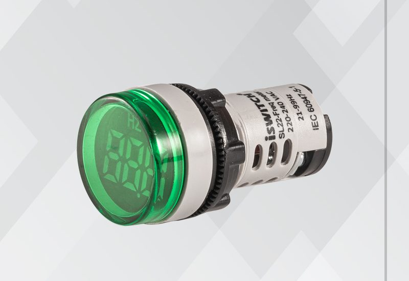
A frequency meter is an instrument that displays the frequency of a periodic electrical signal Various types of frequency meters are used. Many are instruments of the deflection type, ordinarily used for measuring low frequency but capable of being used for frequencies as high as 900 Hz. These operate by balancing two opposing forces. Changes in the frequency to be measured cause a change in this balance that can be measured by the deflection of a pointer on a scale. Deflection-type meters are of two types,electrically resonant circuits and ratiometers. The main principle of working of weston type frequency meter is that “when an current fows through the two coll which are perpendicular to each other, due to these currents some magnetic fields will produce and thus the magnetic needle will deflects towards the stronger magnetic field showing the measurement of frequency on the meter Construction of weston frequency is as compared to ferrodynamic type of frequency meter. In order to construct a circuit diagram we need two coils, three inductors and two resistors.Axis of both coils are marked as shown. Scale of the meter is calibrated such that at standard frequency the pointer will take position at 45”. Coil 1 contains a series resistor marked Rl and reactance coil marked as L1, while the col 2 has a series reactance coil marked as L2 and parallel resistor marked as R2. The indauctor which is marked as LO is connected in series with the supply voltage in order to reduce the higher harmonic me ans here this inductor is working as a filter circuit. Let us look at the working of this meter Now when we apply voltage at standard frequency then the pointer will take normal position, if there increase the frequency of the voltage then we will see that the pointer will moves towards left marked as higher side as shown in the circuit diagram. Again we reduce the frequency the pointer will tart moving towards the right side, if lower the frequency below the normal frequency then it cross the normal position to move towards left side marked lower side as shown in the figure.Now let us look at the internal working of this meter. Voltage drop cross an inductor is directly proportion to frequency of the source voltage, as we increase the frequency of the applied voltage the voltage drop across the inductor Ll increase that means the voltage impressed between the collis increased hence the current through the coil 1 increase while the Current through the coil 2 decreases. Since the current through the coil l increases the magnetic field also increases and the magnetic needle attracts more towards the left side showing the increment in the frequency. Similar action will takes if decrease the frequency but in this the pointer will moves towards the left side. These work by means of tuned steel reeds that vibrate like a tuning fork, under the effect of electric current through a coil; only those reeds that are in resonance vibrate visibly.